DIY Heat Sink for Mellanox Innova-2 Smart NIC
This is a quick show-off post for a heat sink that I made for the Mellanox Innova-2 “smart” NIC. I purchased the NIC in 2021 for less than a hundred dollars from an e-waste recycler on eBay. The board was sold for chip recovery. In particular, there is a Xilinx XCKU15P chip that is worth thousands of dollars even in 2023 according to Digikey and Mouser. However, people in the homelab community soon discovered that the boards they got were actually functional, making the purchase a major steal. I quickly hopped on board and got my own.
The board arrived with no PCIe bracket nor heat sink. The first picture below is how the board should look like (picture from ServeTheHome forum member anything1233) and the second is what I have.
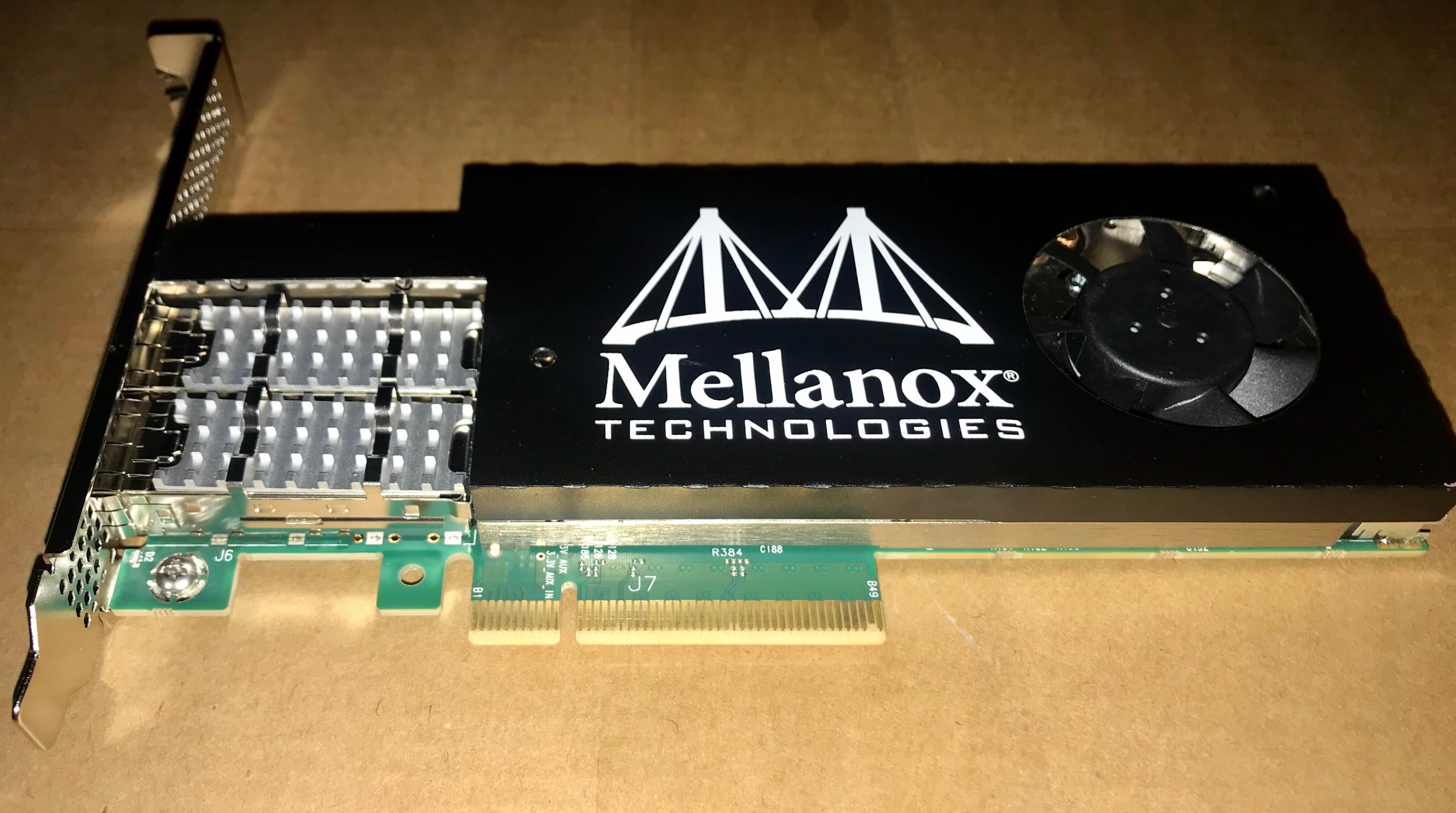
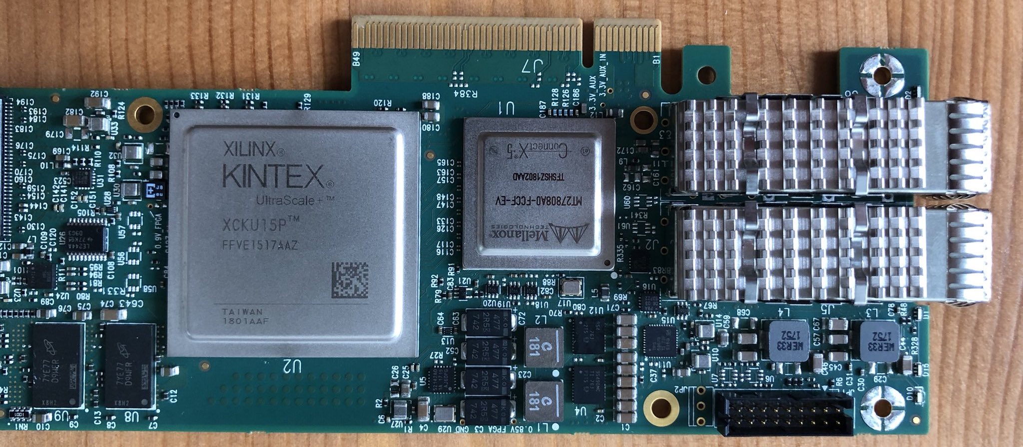
The lack of a bracket (the metal part on the left of the first picture) is fine, because the board is not heavy and will not stress the PCIe socket too much without support from the bracket. The lack of a heat sink (the black metal cover), however, is more troublesome. There are two main chips on the board, one being the FPGA mentioned above and the other being a Mellanox ConnectX-5 25Gbps Ethernet/Infiniband chip. Both are huge heat sources. Without any cooling measures, the Mellanox chip reaches 97 degrees Celsius within minutes with no transceiver module in the SFP28 cage, and the FPGA chip is probably not better (though I do not have a way to measure its temperature). Given the irregular layout of the heat sink mounting holes (the copper-plated holes in the second picture above; three out of four are shown), it seemed hopeless that any aftermarket heat sink would fit. While one could have a Frankenstein solution by strapping a sufficiently large heat sink and a fan on the board (for example this), I wanted a set up that is more aesthetically pleasing.
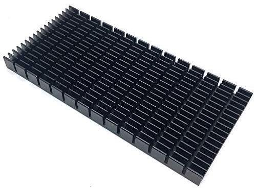
After shelving the board for two years, I decided to make a customized heat sink for the board. I started with a rectangular heat sink like this one.
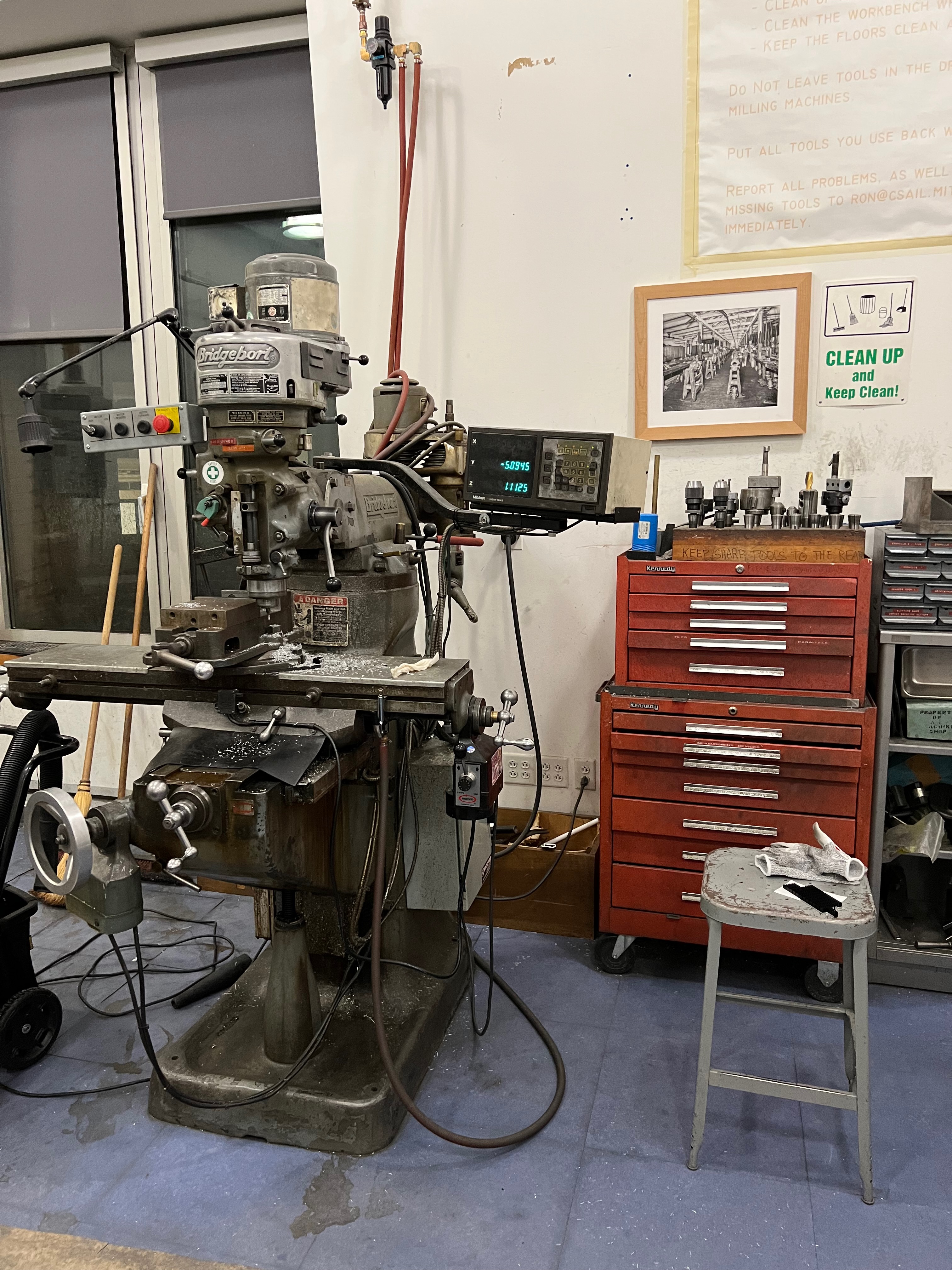
The customizing process was relatively simple. The heat sink should have the same dimensions as the board, and maintain close contact to the chips. I needed to trim the stock part and also carve out the edges to leave space for the various ports and components that are higher than the chips. Then, it should have holes that matches the pre-drilled mounting holes on the board. Without accurate measurements of the board (in particular the mounting holes), I ended up transferring the locations of the pre-drilled holes to a paper card (by drawing through the holes), and then laying the card on the heat sink. This process turned out to be accurate enough. I did the machining using this Bridgeport mill at the CSAIL machine shop.
It took me an evening and an afternoon, but it was a lot of fun using the machine. The final product looks like this.
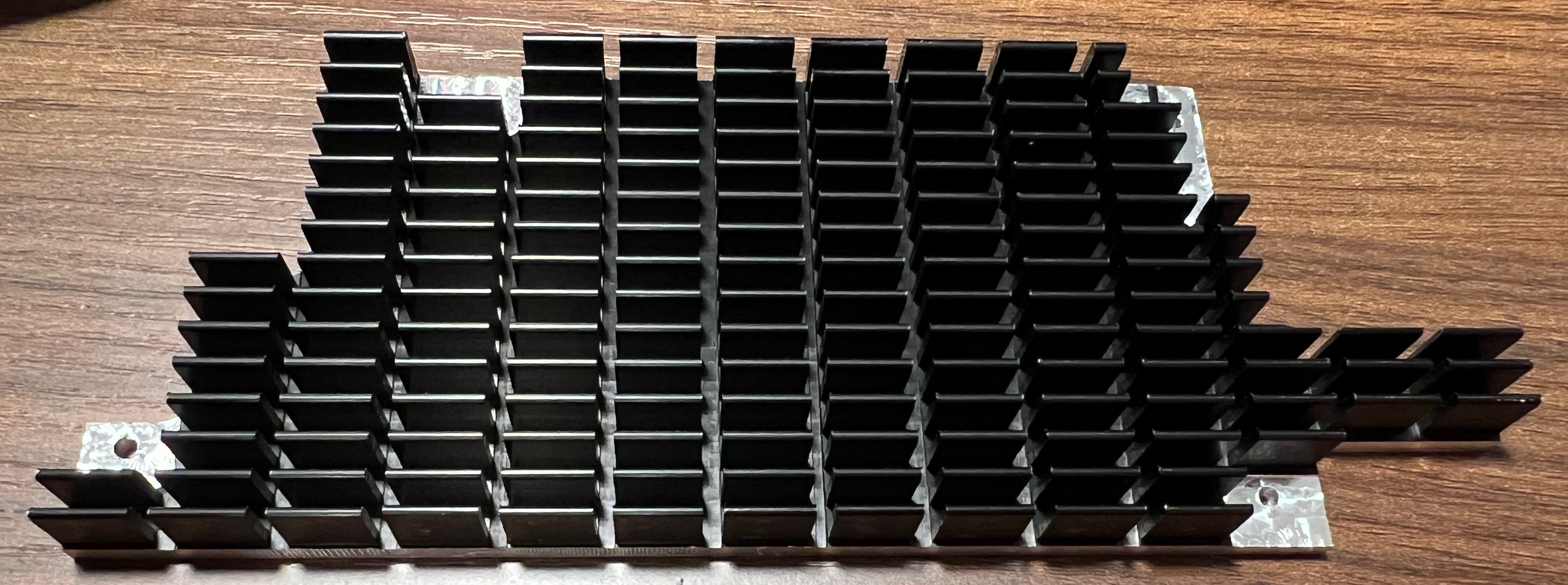
I mentioned that the two chips are of different heights, so I applied a 0.5mm and an 1mm thermal pad to each chip to compensate for the difference. To fix the heat sink to the board, I used four sets of plastic screws, washers, and nuts. I also placed two nuts between the heat sink and the board on each screw as spacers, so that it’s impossible to overtighten the screws and bend the board. This is how the board looks like with the customized heat sink.
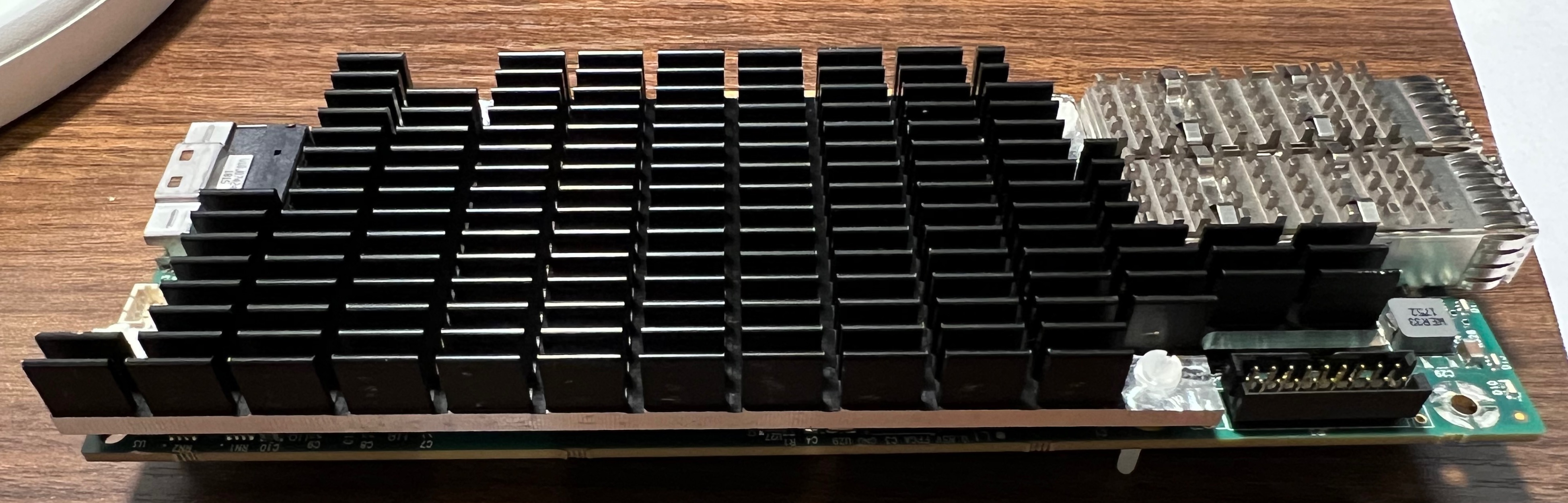
You might notice that the stock heat sink has a fan, while my customized one does not. I decided to forgo the fan for now because of the noise. (The board will be installed in a workstation next to my desk.) This seems to be fine—the Mellanox chip now stabilizes at 82 degrees Celsius compared to 97 degrees without the heat sink. Should the need arise, I can carve out the middle of the heat sink and drill four holes to install a 40mm Noctua fan like the NF-A4x10.