Tearing Down a Humidifier
Last Black Friday, I got an Apple HomePod, so I’m in the process of hooking everything onto HomeKit. (Nesthub, a Nest Thermostat to Apple HomeKit bridge in pure Golang, was my most recent undertaking in this department.) Winters in New England can be pretty dry, so we have a $40 humidifier 1 at home that, well, humidifies the room. Naturally, I want a HomeKit-enabled humidifier. However, Apple’s website lists only one model currently on sale, and that model has a very small water tank which won’t last even a day. Meanwhile, I have a Raspberry Pi Zero W lying around, so it seems a good idea to put the Raspberry Pi into the humidifier to add HomeKit support. After all, everyone wants a humidifier with an 1 GHz ARM processor inside, isn’t it?
The first step of this project is to figure out how the humidifier (especially the mist-making diaphragm) is controlled, i.e., we want to reverse engineer the device. I have some basic knowledge of my humidifier: there is a touch sensor (likely capacitive) that acts as a electronic switch. Two LEDs: one indicates the state of the device (solid blue is on, flashing red is low water), and the other is a decoration that turns on in certain modes. A water level sensor that is likely to be a Reed switch. There should also be an MCU that processes sensor signals and controls the diaphragm.
Time to tear down the humidifier. The screws securing the bottom of the device are covered by the four foam sticker pads, so I tore them off. Then I was able to open the device and look at its inside.
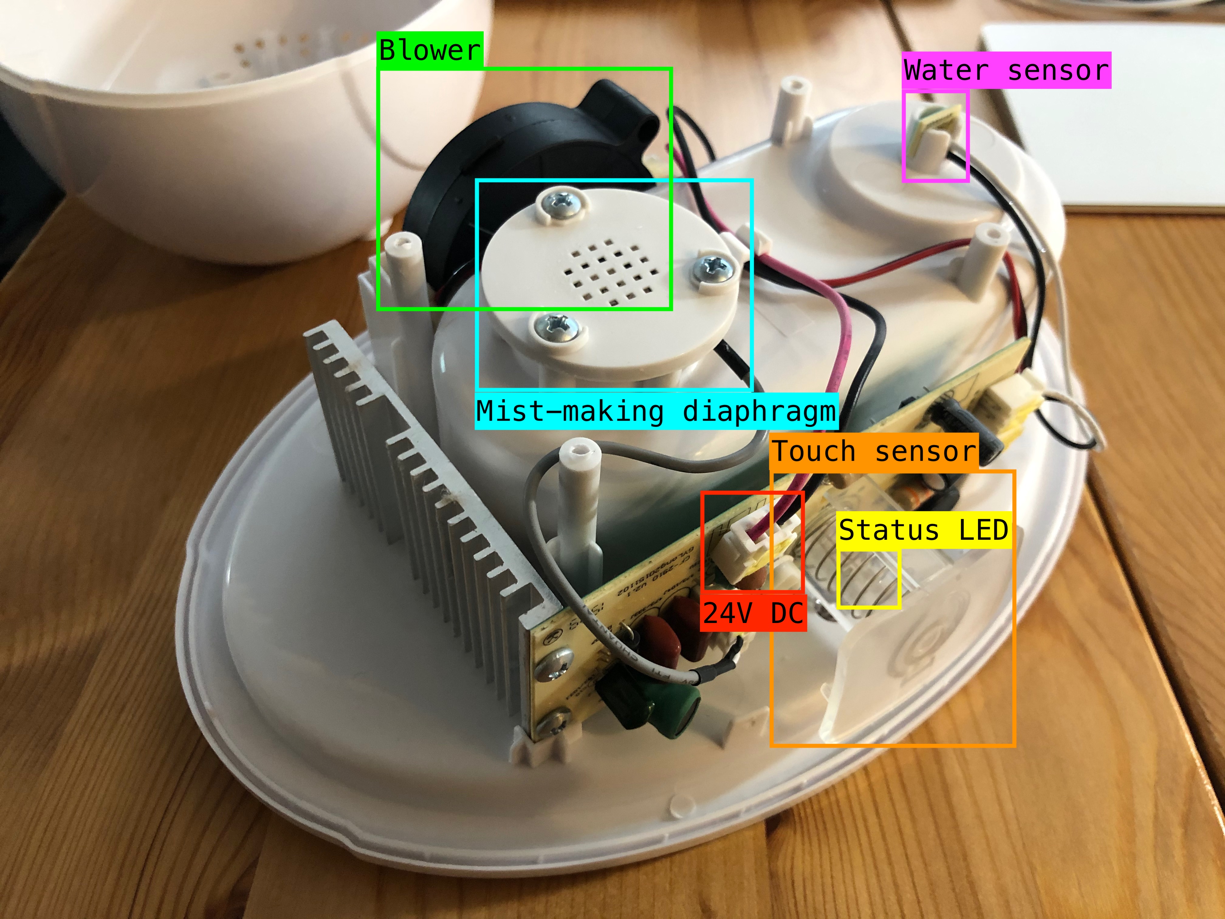
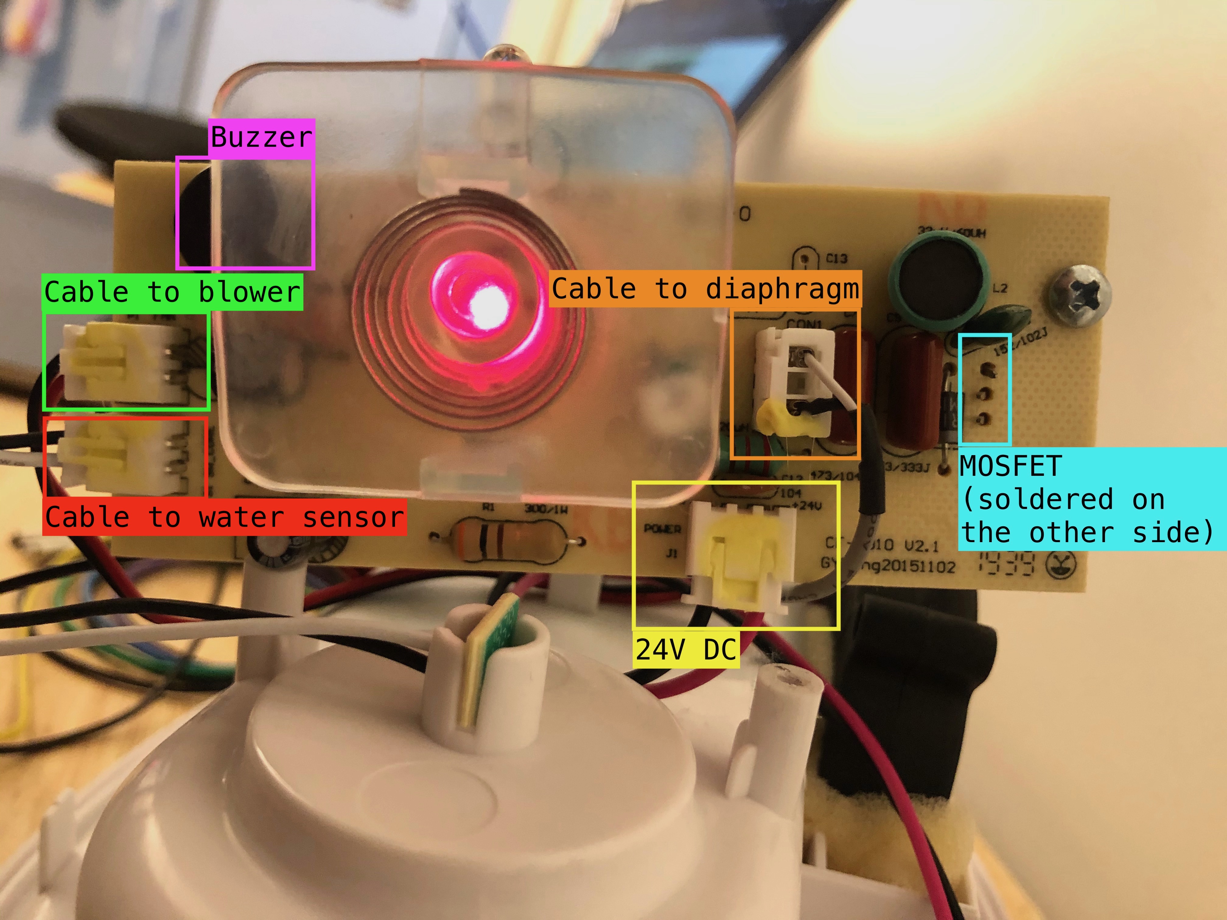
The parts that I anticipated to exist are all there. In addition, there is a blower that blows out the mist. There are some pretty hefty components (mostly capacitors and resistors) on the yellow side of the PCB. To my surprise, there is an oversized heat sink attached to a big component that looks like a MOSFET. The MOSFET, most of the big components, 24V DC input, and a cable leading to the diaphragm share one half of the PCB which supposedly handles high-power and high-voltage (24V) stuff. The blower, the water sensor, and the buzzer share the other half of the board.
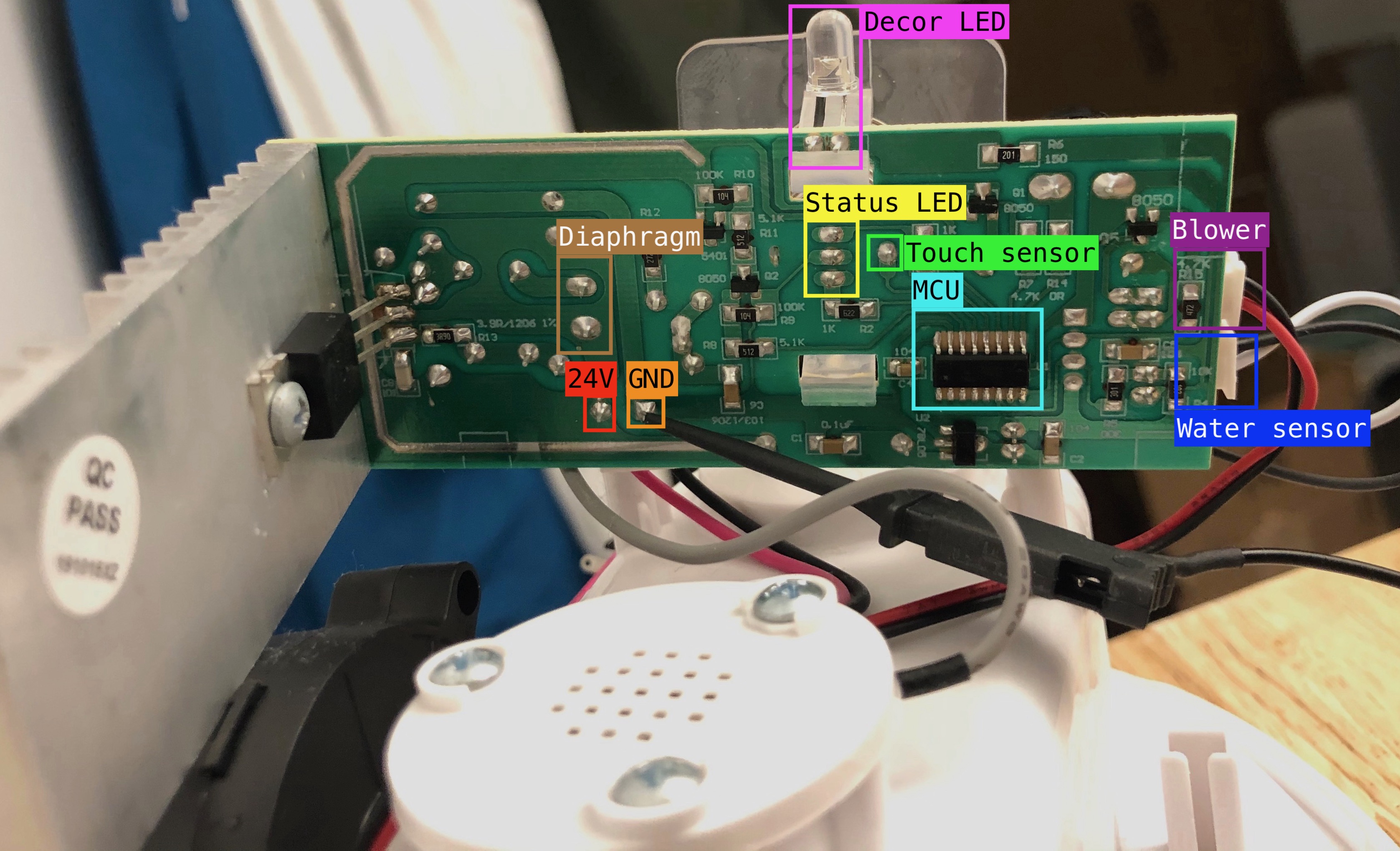
The PCB and the heat sink are simply stuck into the base, so I was able to pull them out easily. I could now see the other (green) side of the PCB. Indeed, there is a MCU that controls everything on the board. By comparing the parts and pins, I was able to match pins on the green side to parts on the yellow side.
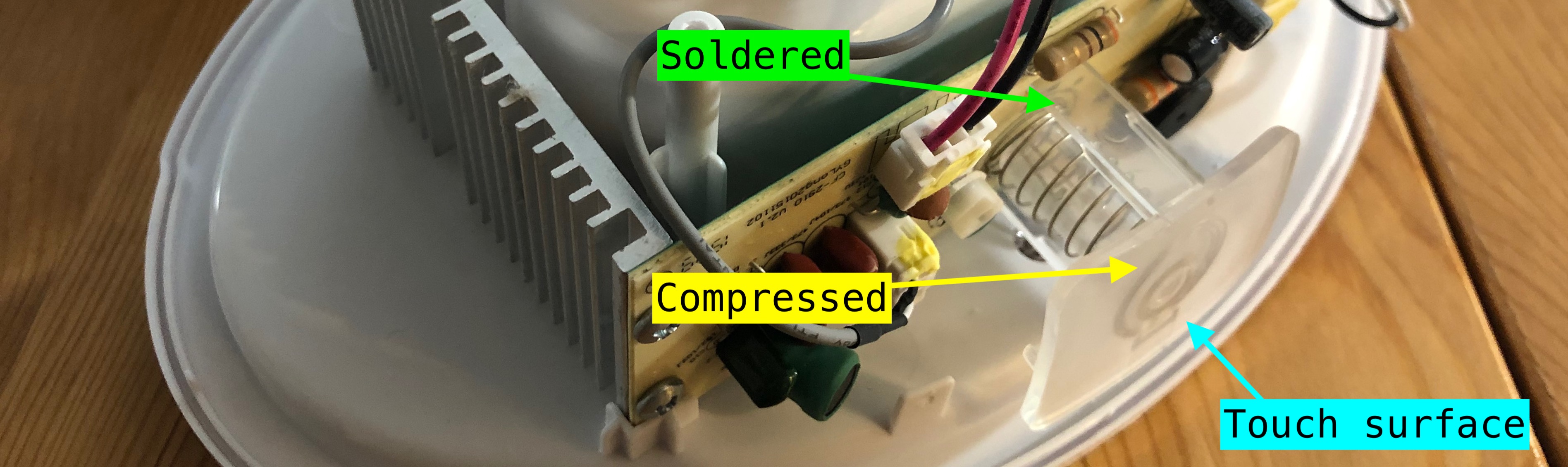
The task now is to decipher every pin on the MCU. The PCB is very simple and seems to only contain one layer, so I effectively have the schematic of the board. My first target was the touch switch. The touch sensor is actually a spring with one end soldered onto the board and the other end compressed by a piece of plastic.
I guess this mechanism works by letting the MCU continuously measure the capacitance of the spring and trigger an event when a change is detected. However, I do not have a more concrete understanding beyond that. Since my goal is to find a way to let my Raspberry Pi take over the control, I wanted to know if there is an easy way for the Raspberry Pi to generate a signal which would be registered as a touch. If so, I can use it to fake touches on the switch and remotely control the humidifier while treating the humidifier as a black box. So I set up my logic analyzer, a Saleae Logic 8.
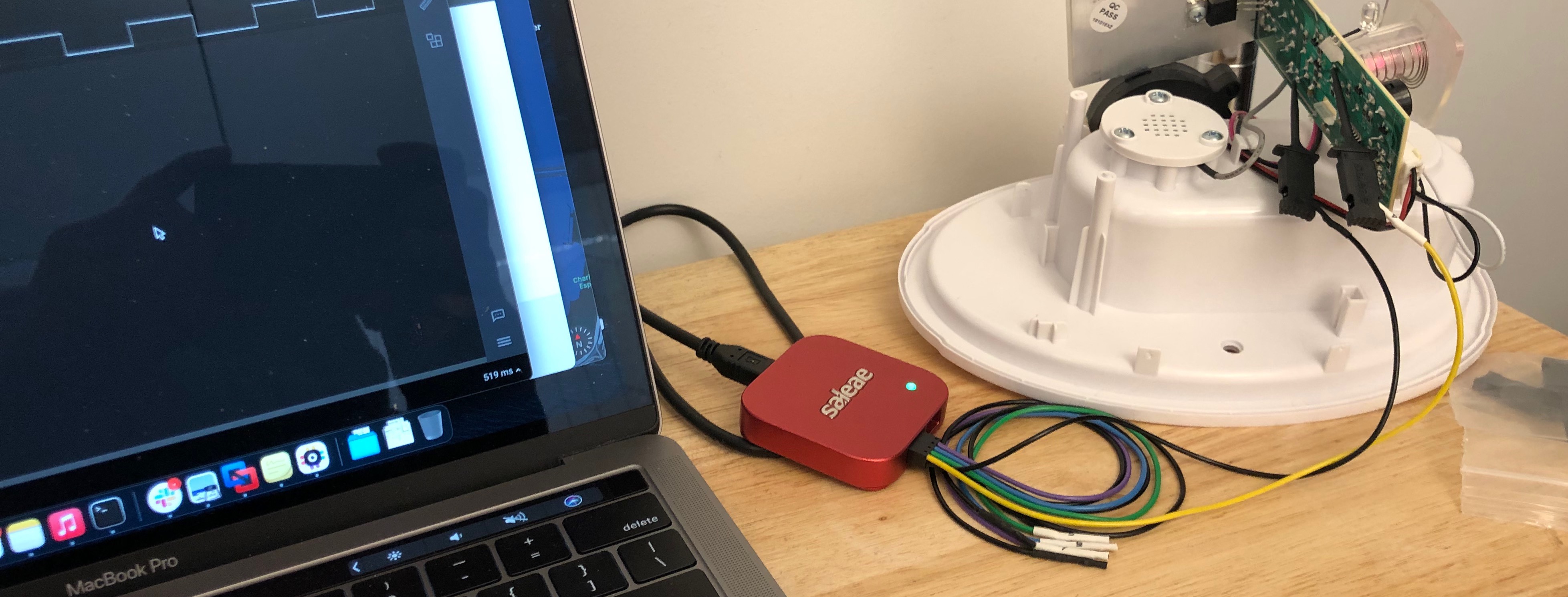
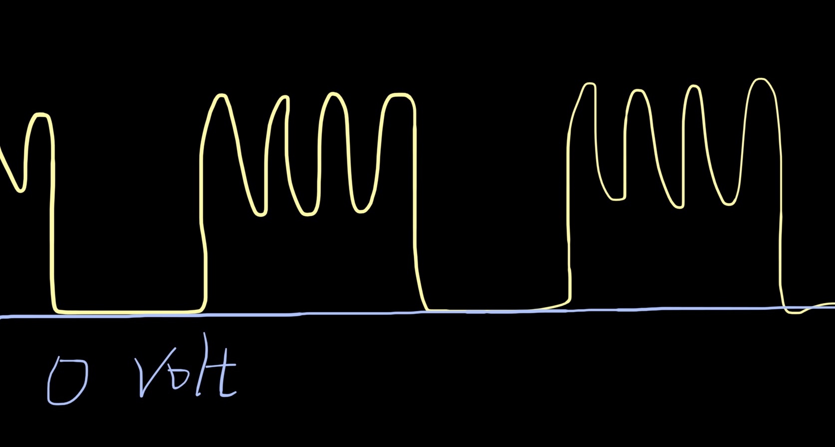
Logic 8 is able to capture both digital and analog signal. Despite its small size, it’s solid and very effective. The logic analyzer shows that the MCU periodically generates a sine wave AC with a DC offset. (I’ve deleted the capture from Logic 8, but the figure below should provide a general idea.) The AC component supposedly helps to measure the impedance of the spring. However, the Raspberry Pi clearly cannot deal with analog signal like this. We have to dig deeper and find other ways to connect it to the humidifier.
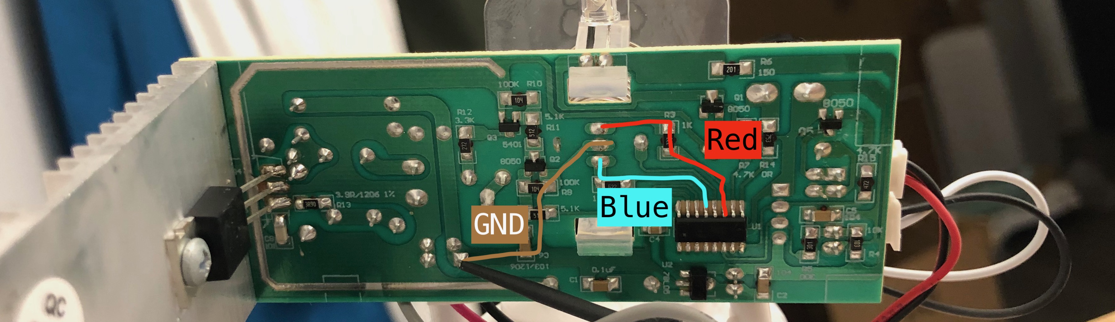
I turned to the status LED next. The LED has three pins and two colors: Red and Blue, so I assume one of them is the cathode and the other two are the anodes for red and blue respectively. According to the PCB, the pin in the middle is connected to the ground, so it must be the cathode. To map the remaining two pins to red and blue, I turned on the humidifier and let the LED flash red due to low water. Then I used the logic analyzer to locate the pin with an on/off signal, and this pin must be for red. The other must be for blue.
Next is the decor LED. I noticed that the status LED is directly drived by the MCU (i.e., the MCU output is responsible
for providing all the power the LED needs by connecting directly to it), so I assumed it’s the case for the
decor LED as well and tried to find a pin that leads straight to the LED. However, there is no such a pin.
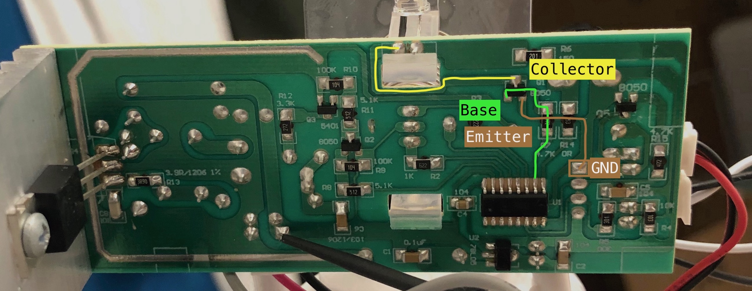
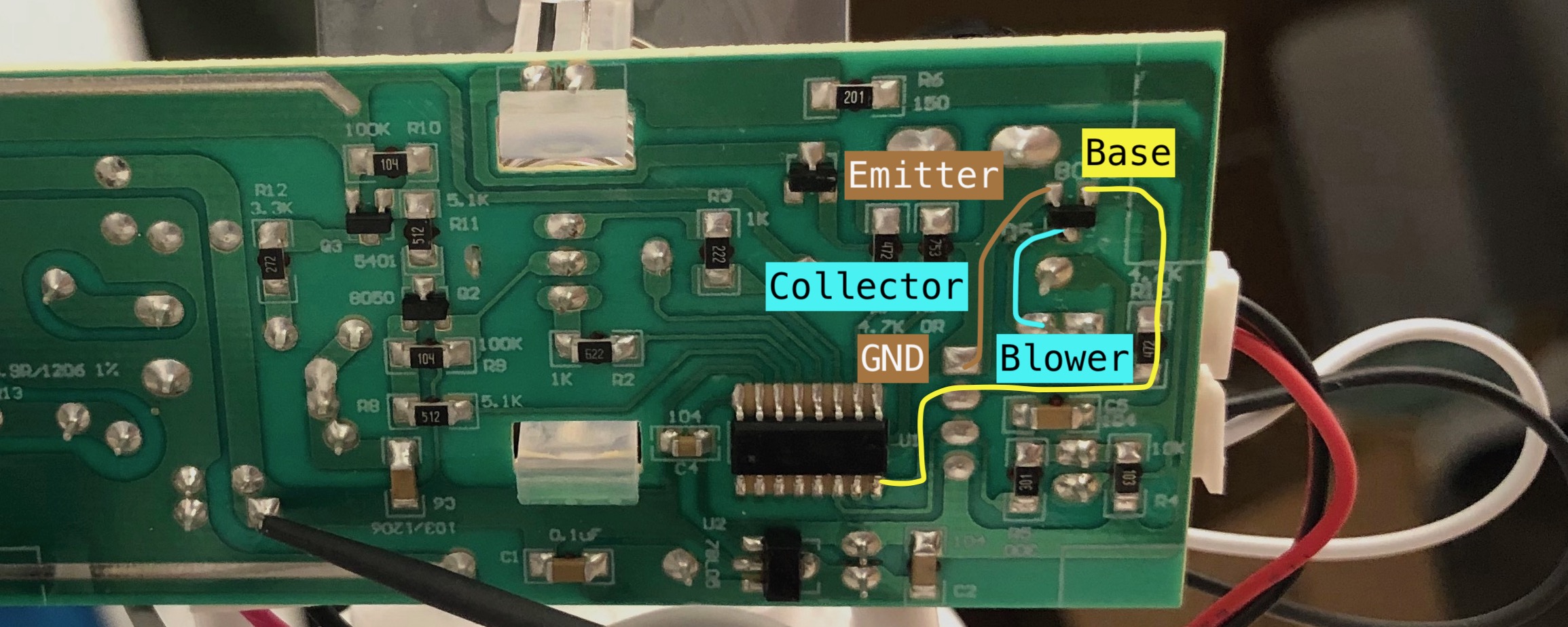
I noticed that one pin of the LED is connected to a three-pin device Q1 8050. A quick search tells me that 8050
is S8050M, an NPN BJT. An NPN BJT has three
pins: Base, Emitter, and Collector. When Emitter has a higher voltage than Base, the NPN BJT works like a switch.
When there is a small current feeding from Base into the BJT, a large current will be drawn from Collector to
Emitter. As a result, we can turn the current from Emitter on/off by controlling the current into Base.
According to the PCB, the Base of the BJT controlling the LED is connected to the MCU. We now know that the MCU
does not directly drive the LED, but rather uses the BJT as a switch.
The blower was similarly controlled through a BJT, so locating the pin on the MCU was a breeze now that we know how to deal with NPN BJTs.
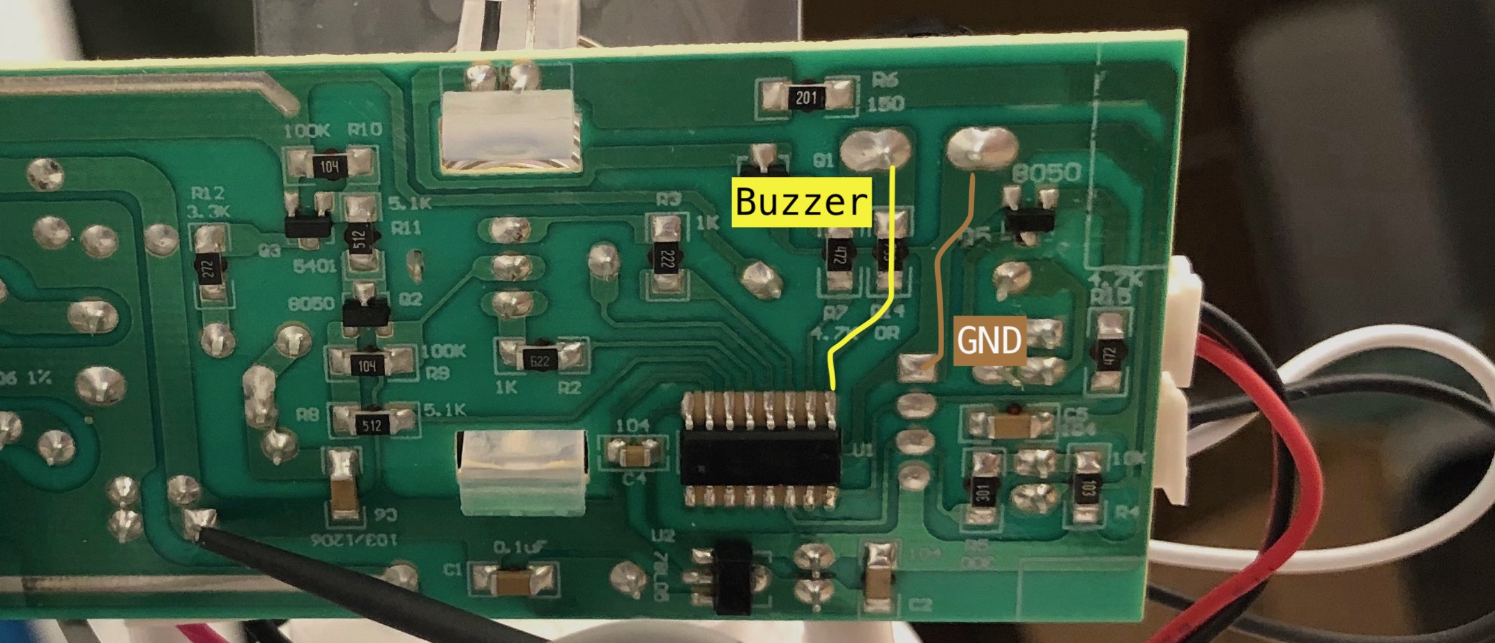
Next is the buzzer. The buzzer is actually directly driven by the MCU, so it’s not hard to locate the pin.
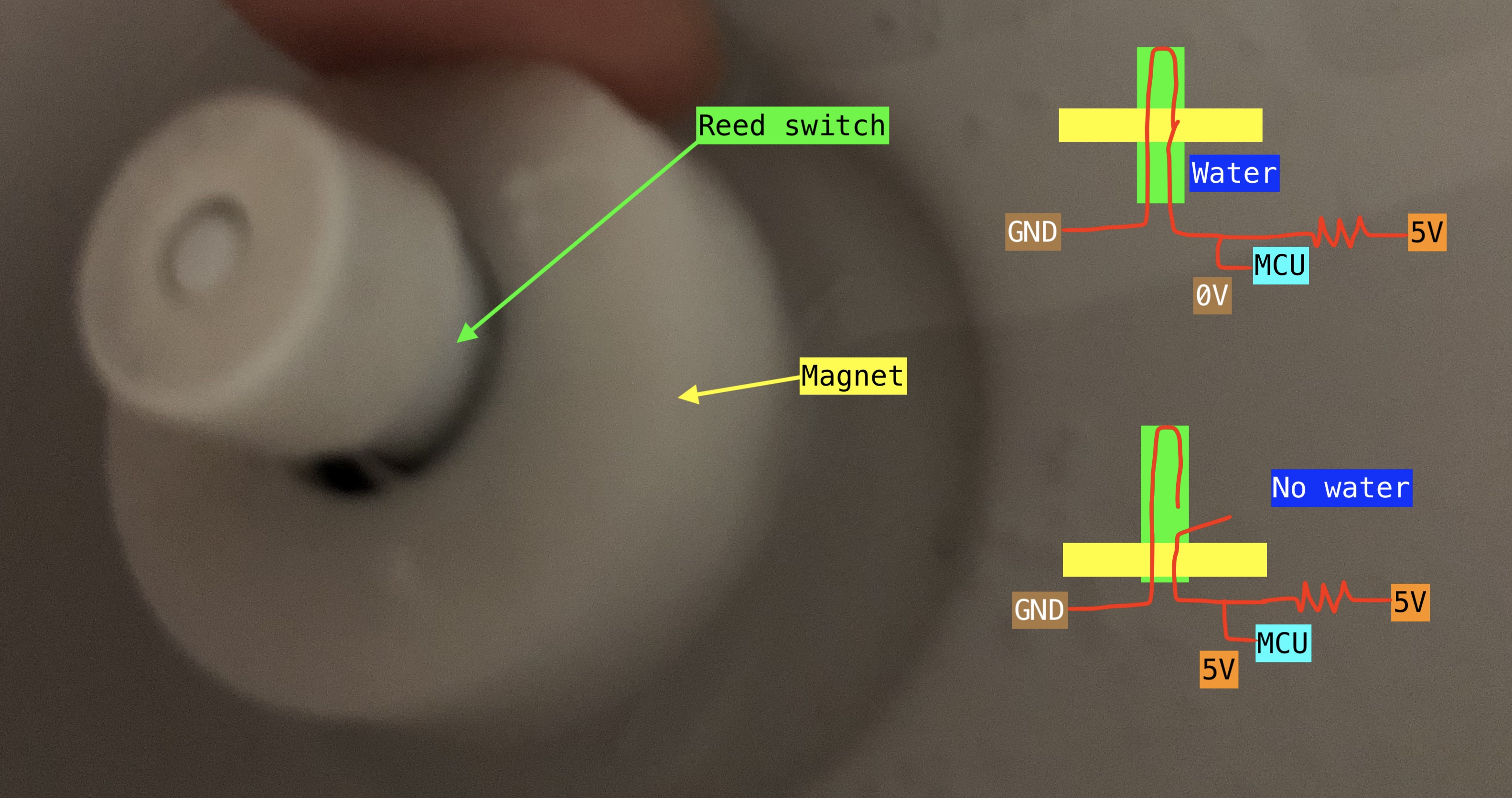
We have two more components left: the mist-making diaphragm and the water level sensor. There is a direct connection from the MCU to one pin of the water sensor. The other pin of the water sensor connects to the ground. But how does the sensor work? The sensor consists of a Reed switch and a magnet. The Reed switch is sealed into a tube, and the magnet can move along the tube. When there is water, the magnet floats such that it activates the Reed switch, and the circuit from the MCU to the ground is closed, and the MCU pin reads low. When there is no water (or when the magnet floats too high), the circuit is open, and the MCU is connected to 5V through a resistor, so the MCU pin reads high. Moving the magnet by hand and reading the MCU pin using the logic ananlyer confirms this theory.
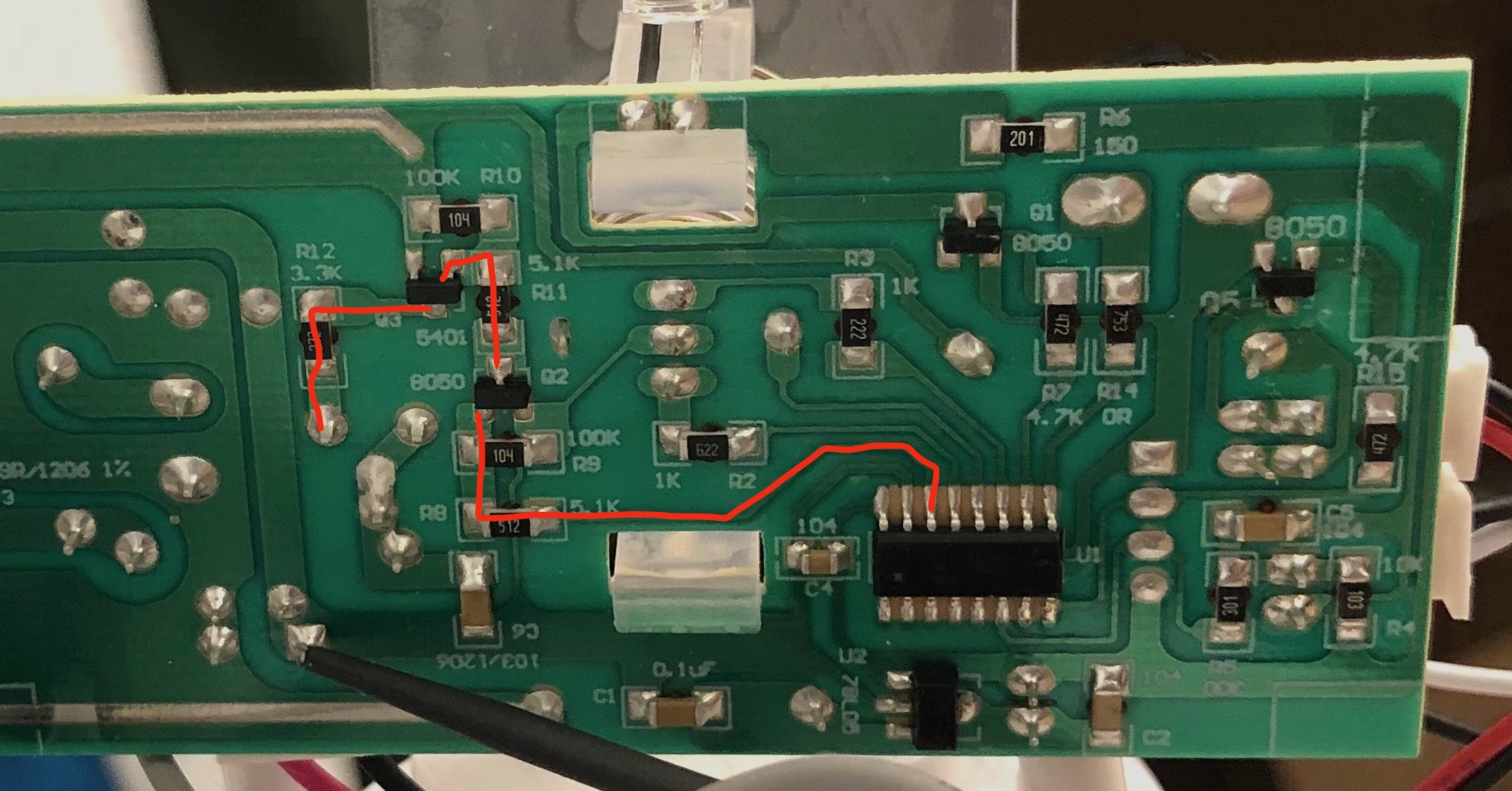
Finally, we look at the diaphragm. The left most pin on the top of the MCU is 5V (VCC), the second left pin is GND,
and we have mapped all other pins to some components. The only pin remaining is the third-left pin, which must be mapped
to the diaphragm. It seems that the diaphragm is driven by two BJTs.
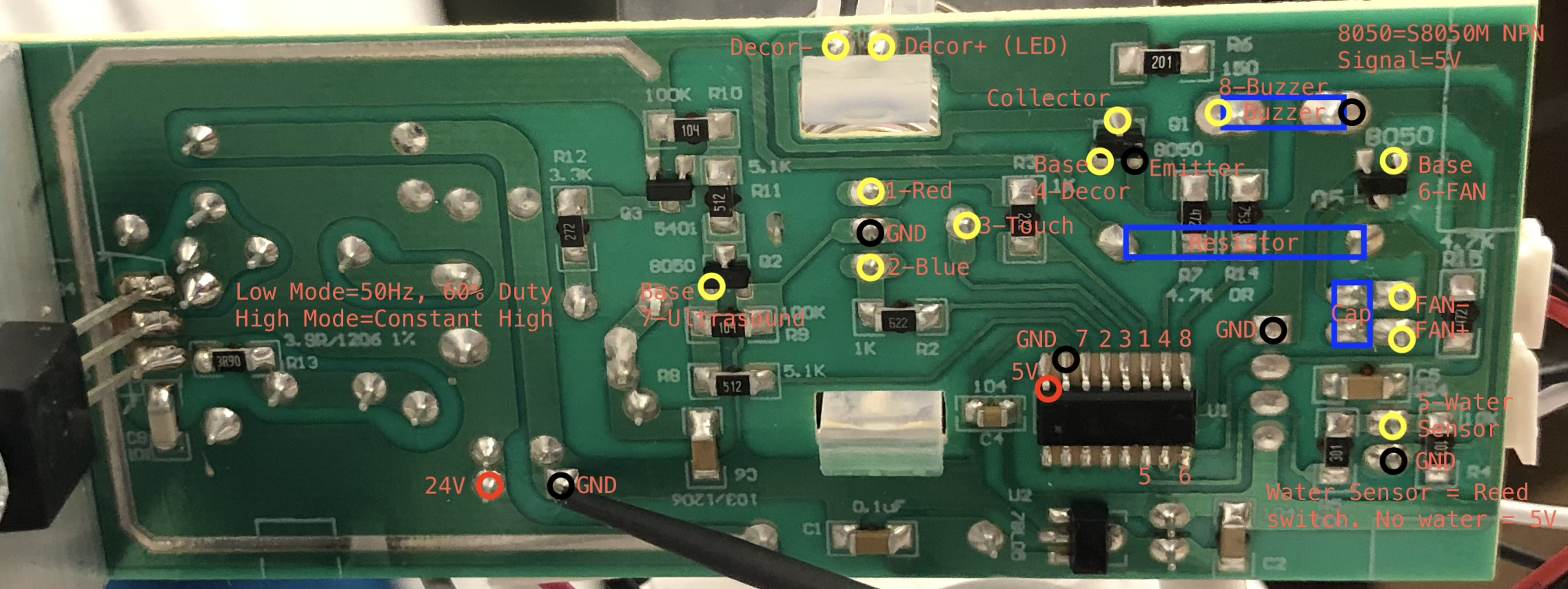
With all pins mapped, I created a figure showing the definition of all pins. To make sure that the MCU does not generate some special waveform to drive the diaphragm, I once again used the logic analyzer. Results show that the MCU generates a constant high signal when the humidifier is on high mode, and a PWM signal of 50 Hz, 60% duty for low mode.
This concludes the first part of the project. We now know how the MCU reads the water sensor and controls the various components on the board. Replacing the MCU with a Raspberry Pi would be easy - at least theoretically. I’d like leave that to another weekend and another post though. Time to reassemble the humidifier and hit the sack.
- The model is “Pure Enrichment MistAire Ultrasonic Cool Mist Humidifier” in case you want to reproduce my results. [return]